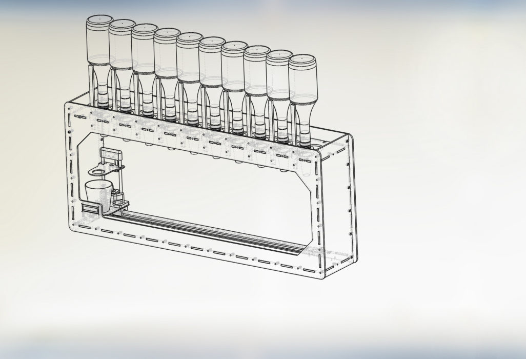
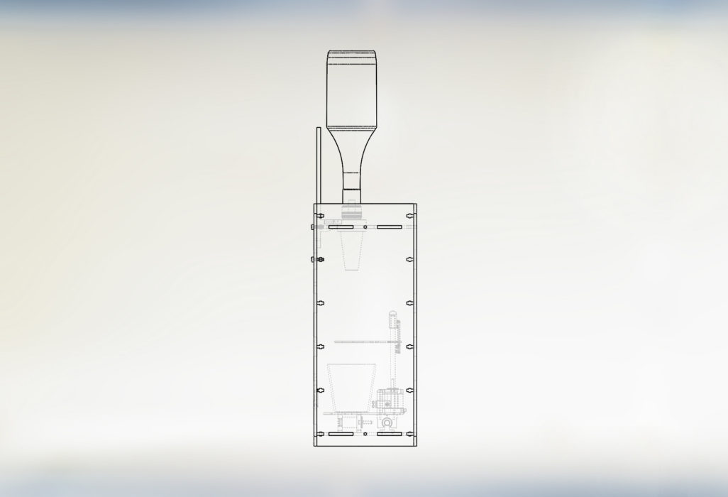
Using a CAD program to design a virtual bartender into a real life robotic bartender:
Before we set-out to build SirMixABot (the world’s self proclaimed greatest robotic bartender) we designed countless iterations in CAD. If you’ve been hiding under a rock for a while, CAD is computer aided design. In the most simple case its a mechanism to make a virtual version of a design before ever spending a dollar on parts. We utilized student license version of Solidworks (thanks MIT and Stanford) in order to make progress on the robotic design, but the principles we’ll go through here apply independent of any CAD problem you’ll have. Before embarking on any project, I keep a few principles in mind.


Keep a frame of reference in your CAD assemblies: Throughout the design, you’ll run into countless decisions of “how big should I make this”? And while a direct measurement of your hand may demonstrate that a 400mm slot may be enough, there’s countless other decisions where you’ll need to think through travel lengths, assembly issues, and worst case motions. Whenever I start designing an assembly I try to keep a few references in mind so that the 3D models can translate into real life easily. For our robotic bartender, we utilized a few frames. The starting point was a simple cup! We rendered a highball glass that was about the same height as my hand and took nearly my full grip to wrap halfway around. Anytime I saw the cup, it was easy to envision how my hand would grab, ingress, or egress to that position. The next frame of reference was of course a typical 750mL bottle. How big is a 750mL? Using these two objects, it was easy to get a good sense of “how tall”, “how wide”, and “how big” any given dimension was in terms of familiar cups or bottles.
Try to get CAD files without developing everything yourself: Need to draw an M5 x 20mm hex head screw? Chances are someone else has already designed that part in CAD before. For many off-the-shelf fasteners, bearings, and machine parts McMaster Carr keeps a great repository of every available CAD part. Rather than design your own, its best to use the most accurate version available.
Furthermore, there are entire communities who have developed other specialized CAD parts for specialized components. A few that come to mind:
- GrabCAD has a rich community of designers (http://www.grabcad.com)
- TraceParts
- 3DContentCentral
Do Not Take Shortcuts: Need to 3d print that part to quickly test? Its rare that designing “just the basics” ever becomes a usable or production part. Instead, you’ll end up 3d printing a piece that simply needs to be thrown away quickly. Furthermore, think through EVERY piece that will be in the assembly, don’t simply stop at the major pieces. Its a mental shortcut to think “I don’t need to figure out where these wiring looms go” only to realize that poorly slap-dashed drill holes can ruin the whole aesthetic or assembly process.
Symmetry tools are your best friend: A lot of CAD and 3D design is simply figuring out the right placement of a few symmetric objects. Amateurs go to the length of drawing every drill hole, dimensioning every gap dimension. Most modern CAD programs have a means to rapidly mirror features (if there’s 2 of them) or create linear patterns (such as 50 drill holes equally spaced).
Using these powerful symmetry mechanisms can sav valuable design initially, but also saves even MORE time when it comes time for the 11th redesign.
Turning the CAD Robotic Bartender into Real Life:
Despite my best-efforts Mix-A-Bot v1 was rubbish. Despite carefully cadding, checking, and rechecking every dimension – the first version left a lot to be desired.
There’s certain things you can’t get right in the virtual world that just need to be tested. Here’s a litany of issues we ran into that only became apparent with real models:


– Ergonomics strangeness: While the CAD models could show the motions of the robotic bartender, and demonstrated the functional capability of the machinery they still didn’t capture what it was like to load a bottle, or place a Cup into the tray. It became apparent that at certain heights, it might be really difficult to load. Or given a large cup, that tilting the cup int the slot became precarious.
– Clearance Issues: Despite reading about “best practice” clearances for holes, slots, and tabs, the Mix-A-Bot still had clearance issues. It turns out not every machine has perfectly predictable error rates, and assembling a prototype on a laser cutter with inconsistent 0.2mm errors could cause meaningful errors.
– Can we Add … : Now that its all together wouldn’t it be nice if we added LED’s? Inevitably having the complete assembly in front of you gives the inspiration for even more ideas and concepts for the next version.
– Difficulty in Assembly: That tight clearance you had put against the back wall? It turns out its really hard to get an Allen wrench in that slot. The process of mating two parts on a computer is very different than holding two heavy pieces together and trying to hold them in place while turning two bolts simultaneously.


