
Now that the barbot internals are assembled, it’s time to finalize SirMixABot’s wiring. The main components include an Arduino microcontroller, motor shield, I2C shield, and buck converter. Although the main wiring harness comes assembled, linking to components is still required for kit assembly. Use the diagrams to connect stepper motors, limit switches, LCD screen, and more.
Completing the Wiring for the Barbot
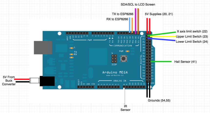
Now that the electronic are mounted it’s time to wire everything up. A wiring diagram to the Arduino and between electronic components is provided below, but a few notes beforehand.
- The Variable DC power supply should be set to 9V before proceeding
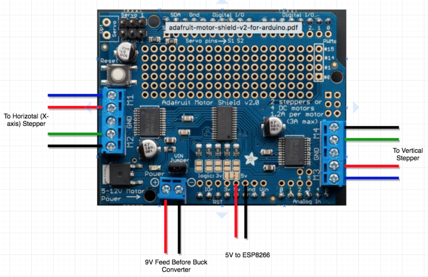
- All motor components run from the 9V power supply
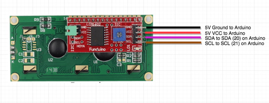
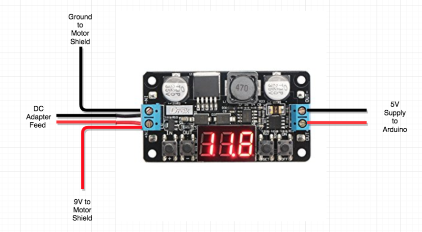
- All Arduino Components run from the 5V supplied by the buck converter. You can tune the buck converter to a 5V output after connecting the 9V to the “IN”. The wires are labeled red and black for positive and negative terminals. The LCD screen should show the voltage amount.
Wiring Diagrams:
These components are used for their durability, straight-forward interface, and customization potential. We also discuss why we used the Arduino Mega 2560 microcontroller. The technologically-inclined can use SirMixABot as a platform to further customize. From custom lighting, to voice commands, we’re excited to see what features are included in future bots. With the wiring done, it’s time to move on and start up your automatic cocktail maker. Grab your glass – it’s time for a drink!